Categories
- RF Knowledge (4)


In addition to frequency range, voltage standing wave ratio (VSWR), and insertion loss, the correct selection of RF cable assemblies must also consider the mechanical characteristics of the cable, the operating environment, and the application requirements. RF coaxial cables are generally divided into four types: semi-rigid, corrugated, semi-flexible, and flexible cables. Different types of cables should be selected for different application scenarios. Semi-rigid and semi-flexible cables are typically used for internal interconnections within equipment; corrugated cables were traditionally used in base station construction, while flexible cables are mainly used in test and measurement applications. This article will briefly explain the common indicators of RF coaxial cables.
1.1 Semi-Rigid Cable
As the name implies, this type of cable is not easily bent into shape. Its outer conductor is made of aluminum or copper tubing (with plating, typically tri-metal alloy). It has very low RF leakage (< -120 dB), making signal crosstalk in the system negligible. The passive intermodulation (PIM) performance of this cable is also excellent.
To bend it into a specific shape, a dedicated forming machine or hand tools are required. This complex manufacturing process results in highly stable performance. Semi-rigid cables use solid polytetrafluoroethylene (PTFE) as the dielectric material, which has excellent temperature stability—especially under high-temperature conditions—ensuring good phase stability. Although semi-rigid cables are more expensive than semi-flexible cables, they are widely used in various RF and microwave systems. However, with the acceleration of product updates, their usage has decreased somewhat.
1.2 Semi-Flexible Cable
Semi-flexible cables serve as an alternative to semi-rigid cables. Their performance is close to that of semi-rigid cables, and they can be manually formed. However, their stability is slightly inferior to semi-rigid cables. Due to their ease of forming, they are also more prone to deformation, especially after long-term use.
1.3 Flexible (Braided) Cable
Flexible cables are often referred to as “test-grade” cables. Compared to semi-rigid and semi-flexible cables, flexible cables are more expensive, as their design must consider more factors.
Flexible cables must maintain performance after repeated bending, which is the most basic requirement for test cables. Softness and good electrical performance are somewhat contradictory, and this contradiction is a major reason for their high cost. When selecting a flexible RF cable assembly, various factors must be considered simultaneously, and some of these factors may conflict with each other. For example, coaxial cables with a single-strand center conductor have lower insertion loss and better amplitude stability under bending than multi-strand conductor cables, but their phase stability is inferior. Therefore, in selecting a cable assembly, in addition to frequency range, VSWR, and insertion loss, the mechanical properties, operating environment, and application requirements must also be considered. Cost is also always an important factor.
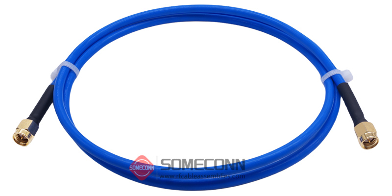
Example: RG402 semi flexible coaxial cable, SMA male to SMA male connector
2.1 Characteristic Impedance
An RF coaxial cable consists of a conductor, dielectric, outer conductor, and jacket. “Characteristic impedance” is one of the most frequently mentioned indicators in RF cables, connectors, and cable assemblies. Maximum power transfer and minimum signal reflection depend on the impedance matching between the cable and other components in the system. If the impedance is perfectly matched, the cable loss is only due to the transmission line’s attenuation, without any reflection loss.
The characteristic impedance (Zo) of the cable is related to the ratio of the inner and outer conductor dimensions. Due to the “skin effect” of RF energy transmission, the critical dimensions affecting impedance are the outer diameter of the inner conductor (d) and the inner diameter of the outer conductor (D):
Zo(Ω) = ( 138 / √ε ) x ( log D/d )
Most RF cables used in communication applications have a characteristic impedance of 50Ω, while 75Ω cables are commonly used in broadcast television.
2.2 Voltage Standing Wave Ratio (VSWR) / Return Loss
In RF and microwave systems, maximum power transfer and minimum signal reflection depend on the impedance matching between the RF cable and other system components. Variations in cable impedance can cause signal reflections, which result in a loss of incident wave energy. The magnitude of reflection is expressed as the Voltage Standing Wave Ratio (VSWR), which is defined as the ratio of incident to reflected voltage:
VSWR= ( 1 + √Pr/Pi) / (1 – √Pr/Pi)
Where Pr is the reflected power and Pi is the incident power.
A smaller VSWR indicates better consistency in cable manufacturing. An equivalent parameter to VSWR is the reflection coefficient or return loss. The typical VSWR of microwave cable assemblies ranges from 1.1 to 1.5, corresponding to return loss values between 26.4 dB and 14 dB. This means the transmission efficiency of the incident power ranges from 99.8% to 96%. For example, if the input power is 100W and the VSWR is 1.33, the output power will be 98W, with 2W reflected back.
2.3 Attenuation (Insertion Loss)
Attenuation indicates the cable’s ability to effectively transmit RF signals and consists of three components: dielectric loss, conductor (copper) loss, and radiation loss. Most of the loss is converted into heat. Larger conductor sizes result in lower loss, while higher frequencies lead to higher dielectric losses. Since conductor loss increases with the square root of frequency and dielectric loss increases linearly with frequency, dielectric loss typically dominates the total loss.
Additionally, increasing temperature raises the resistance of the conductor and the dielectric loss factor, thereby increasing overall loss. For test cable assemblies, the total insertion loss is the sum of connector loss, cable loss, and mismatch loss. Improper handling during use can also introduce additional loss. For example, bending a braided cable increases its loss. Each cable has a minimum bend radius specification. When selecting a cable assembly, first determine the acceptable loss value at the system’s highest operating frequency, and then select the smallest cable size that meets this requirement.
2.4 Average Power Rating
The average power rating refers to the cable’s ability to dissipate heat generated by resistive and dielectric losses. In practical use, the effective power of the cable is related to VSWR, temperature, and altitude:
Effective Power=Average Power x VSWR Factor x Temperature Factor x Altitude Factor
When selecting a cable, all of the above factors should be considered.
2.5 Velocity of Propagation
The velocity of propagation (Vp) is the ratio of the signal speed in the cable to the speed of light. It is inversely proportional to the square root of the dielectric constant:
Vp = (1 / √ε) x 100
From the above equation, it is clear that the lower the dielectric constant (ε), the closer the propagation speed is to the speed of light. Therefore, cables with low-density dielectrics have lower insertion loss.
2.6 Phase Stability Under Bending
Phase stability under bending refers to the change in phase that occurs when the cable is bent. Bending during use affects the insertion phase. Reducing the bend radius or increasing the bend angle will increase phase variation. Similarly, repeated bending also leads to increased phase variation. Phase variation is generally linearly related to frequency. Cables with low-density dielectrics have significantly better phase stability than those with solid dielectrics.
2.7 Passive Intermodulation (PIM) Distortion
Passive intermodulation (PIM) distortion is caused by nonlinearities within the cable. In an ideal linear system, the output signal is identical to the input signal. In a nonlinear system, however, the output signal will exhibit amplitude distortion compared to the input.
If two or more signals are simultaneously input into a nonlinear system, intermodulation distortion will generate new frequency components at the output. In modern communication systems, engineers are particularly concerned with third-order intermodulation products (such as 2f1–f2 or 2f2–f1), as these unwanted frequencies often fall within the receiver band and can cause interference to the receiver.